
Function of each surface
The locating surface, guiding section, shoulder and fastening thread are distinguished so their tolerances serve the intended function.
Bring locating pins, locking parts and special screws together with drawing-based sourcing requirements.
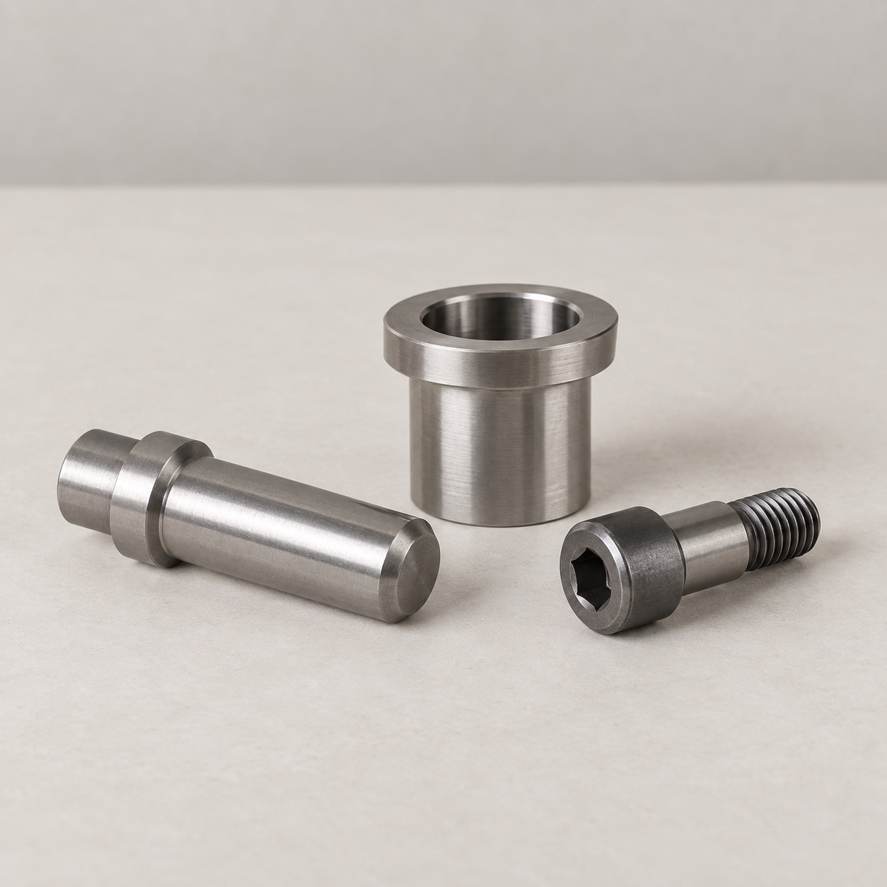
These are specification options within the same family. Actual availability and suitability are confirmed against your request.
Do not assume a collar style from the bore diameter. State the approved configuration.
A commercial screw name cannot replace non-standard dimensions or treatment requirements.
Locking part covers many different designs. Provide the actual part drawing before feasibility review.
Nominal inside and outside diameters do not define locating fits. Include tolerances and the approved installation requirement.
A thread size alone does not define the pin or operating arrangement. Preserve the full reference and option code.
A total length does not define shoulder positions or retention geometry. Include a drawing with datum references.
A nominal shaft size does not specify every ring or groove requirement. Use the approved reference and mating drawing.
A screw thread does not identify the contact geometry or adjustment arrangement. Include the equipment requirement or drawing.
For brand distribution, China-made components and drawing-based parts, origin, specifications and supply terms are confirmed by item.
Locating parts establish position; fastening parts hold the assembly. Their fit, contact surfaces and material condition are linked to the drawing and mating component.
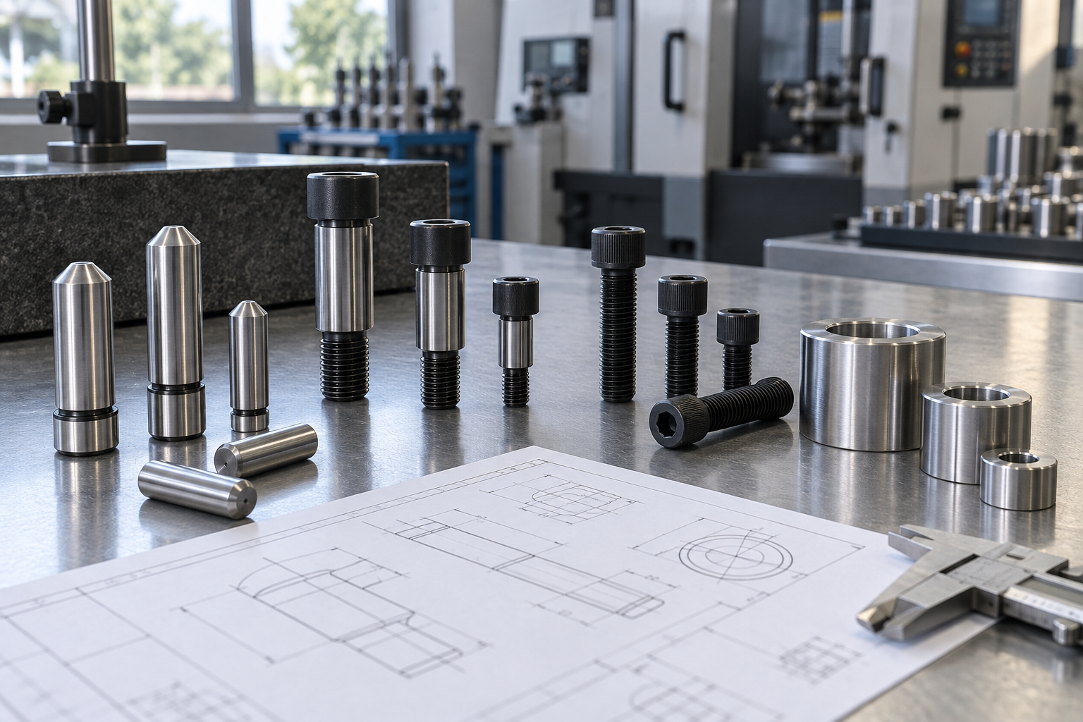
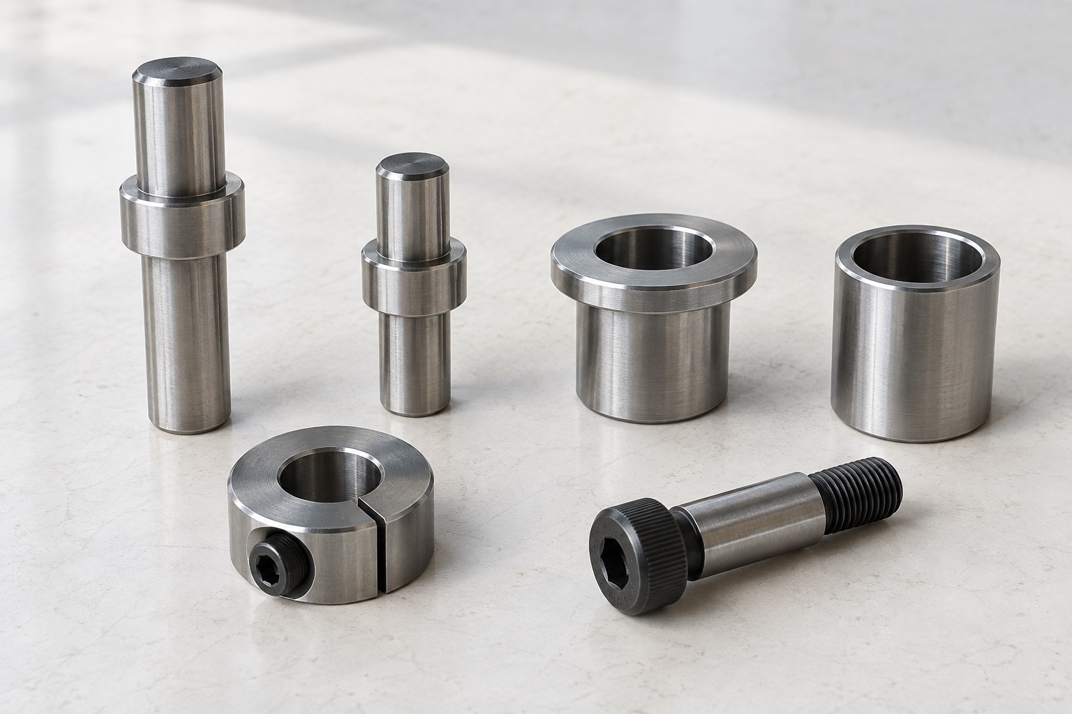
| Product form | Construction | Selection focus | Connected components |
|---|---|---|---|
| Locating pins | Cylindrical or shaped locating head with a mounting shank | Locating datum, head geometry and fit direction | Mating bushings and fixture plates |
| Locating bushings | Sleeve provides the mating locating surface | Inside fit, outside retention and replacement method | Locating pins and receiving holes |
| Shoulder screws | Defined shoulder and threaded fastening section | Shoulder length, bearing surface and thread engagement | Guided, pivoting or spaced components as drawn |
| Locking and special fasteners | Threaded or clamping geometry follows the connection | Contact geometry, tool access and retention method | Shafts, bearings, pulleys and drawing-based spacers |
The locating surface, guiding section, shoulder and fastening thread are distinguished so their tolerances serve the intended function.
A pin and bushing are considered with their mounting holes and assembly direction, including planned replacement and disassembly.
Material, heat treatment and surface finish are kept with the drawing revision because these can affect final dimensions and fit.
Locating and fixing elements connect the rail and carriage arrangement to the machine reference surfaces.
Linear GuidesSpacers and locking parts complete the pulley-to-shaft connection around the approved drawing.
Timing Pulleys & BeltsCollars, locknuts and related parts are matched to the bearing arrangement and shaft interfaces.
BearingsA model, photo, drawing or BOM can start the discussion; brand, quantity and critical interfaces can be clarified by item.
Specified brands, China-made parts and drawing-based components, reviewed against one equipment list.